HALT procedures vary from lab to lab but are typically performed similar to DES’s procedure which is summarized below. DES’s HALT procedure is divided into 5 Stages: Stage 1 – Temperature Step Stresses, Stage 2 – Temperature Ramps, Stage 3 – Vibration Step Stresses, Stage 4 – Combined Temperature &Vibration Stresses, and Stage 5 – Temperature Destruct Limits.
Stage 1 is used to determine the HALT Operational Limits for temperature. The goal is not to cause destruction in Stage 1, but sometimes the operational and destruct limits occur simultaneously. The HALT Destruct Limits for temperature and vibration are typically found in Stages 3 to 5.
Temperature Step Stresses – Stage 1 (Figure 1)

Stage 1 is started with Cold Step Stresses. Testing is started at 10ºC and is decreased in 10 ºC increments until the lower operating limit is determined or the chamber minimum temperature of -100 ºC is reached.
The dwell time at each step is defined as the point when stabilization and saturation of the device and its components is achieved which is typically 15 to 20 minutes. Functional testing will occur during this stabilization period. The dwell time will be determined from temperature measurements obtained from thermocouples placed on the product. Thermocouple data from individual components that can be a source of heating or cooling are not used to define the dwell time.
The second part in Stage 1 is Hot Step Stresses. Testing is started at 40 ºC and increased in 10 ºC increments until either the upper operating limit is determined or the chamber maximum temperature of +200 ºC is reached. The dwell time will be established using the same procedure as for the Cold Step testing segment.
Note that the upper and lower temperatures may be reduced if material limitations, i.e., solder melting or plastic softening are exceeded. Also, it is good practice to perform a functional test of the product at room temperature or 25 ºC before starting a HALT to get baseline measurement on its performance.
Temperature Ramps – Stage 2 (Figure 2)

During this Stage, temperature cycles with rapid transition rates (ramps) will be applied to the product. The chamber air temperature will be changed at 60 ºC/minute. The hot and cold temperatures will typically range from 10 ºC above the lower operating limit to 10 ºC below the upper operating limit. These 10 ºC reductions are to allow for over shooting caused by changing the temperatures extremely fast. The dwell time, established in Stage 1, will normally be used at each hot and cold temperature. Five cycles are applied.
Vibration Step Stresses – Stage 3 (Figure 3)
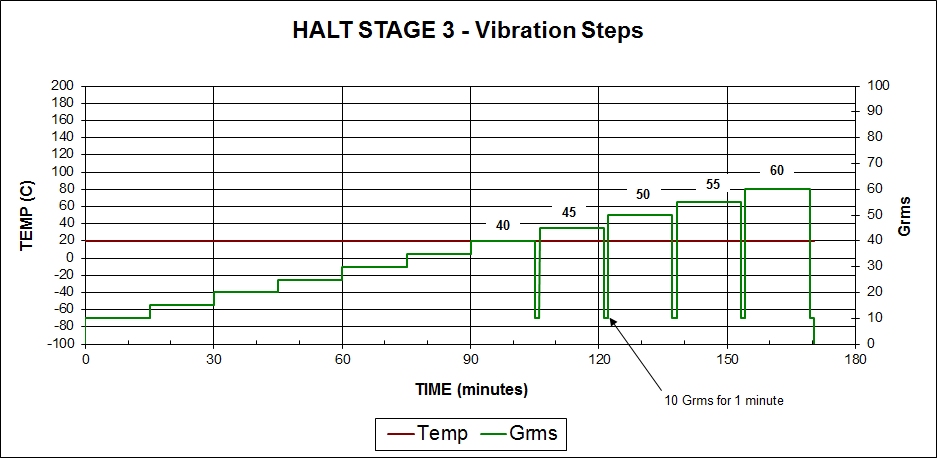
A broadband vibration spectrum will be applied through the HALT chamber table. The HALT chamber table should apply random vibration energy to 10,000 Hz in 6 DOF (degrees of freedom). Vibration step stresses will start at 10 Grms and increase in 5 Grms steps until either the operating, the destruct limits, or the chamber maximum vibration level of 60 Grms is reached. At 40 Grms levels and above, the vibration step will be returned to 10 Grms for 1 minute to detect failures that could be hidden by extreme forces occurring at higher vibration levels. Dwell time at each step, will be approximately 15 minutes to accumulate fatigue damage. Grms is measured with a 5 KHz bandwidth. This test is performed at room temperature of approximately 20 to 25 ºC.
Combined Temperature & Vibration Stresses – Stage 4 (Figure 4)
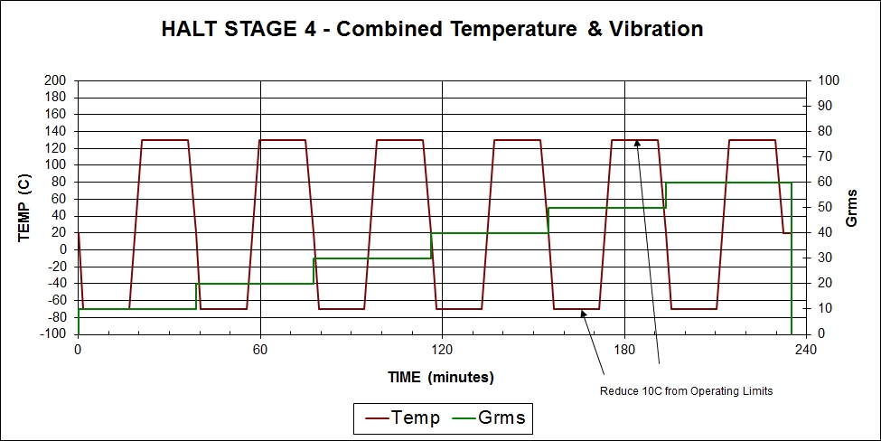
Combined temperature and vibration stresses are applied in Stage 4. During this Stage, the chamber air is changed at 60 ºC/minute. The hot and cold temperatures are the same as those used in Stage 2. The dwell time at each hot and cold temperature will be the same as used in Stage 2. Vibration level is fixed during each temperature step and begins at 10 Grms and increases in 10 Grms steps until either the operating or destruct limits or the chamber maximum vibration level of 60 Grms is reached.
Temperature Destruct Limits – Stage 5 (Figure 5)

The cold temperature destruct limit is found by starting at the lower operating limit (found in Stage 1) and decreasing the temperature in 10 ºC increments until either the low temperature destruct limit or the chamber minimum temperature of -100 ºC is reached. The hot temperature destruct limit is found by starting at the upper operating limit (found in Stage 1) and increasing the temperature in 10ºC increments until either the hot temperature destruct limit or chamber maximum temperature of 200 ºC is reached. The dwell time established in Stage 1 is used typically, however dwell times may be reduced if the product stops operating or if failures occur. If the product fails to operate, the temperature will be reduced or increased towards 20 ºC to see if the product recovers. If the unit is non operational after stabilizing at 20 ºC, the product will be repaired (if practical) so that the test temperatures can be expanded. If it is not practical to repair the product, Stage 5 will be terminated.
Power On/Off Cycling
Powered on/off cycling is recommended at every temperature or vibration step to create additional electrical stresses. These power cycles will be conducted quickly but sufficient time will be allowed so as not to create artificial excessive overloads and failure modes. Powered on/off cycling may not be appropriate for every product as it may create artificial stresses and failure modes, or the product may take too long to power up.
Test Samples
The typical number of products tested simultaneously is 1 to 4 as practical based on the cost and size of the products. Additional spare parts or backup units (not under test) may be needed for spare parts to repair and continue with testing if a non-repairable failure occurs.
Test Reporting
High quality test reports written by DES will contain, at a minimum, plots similar to those shown in Figures 1 to 5. These plots will include measured chamber control temperature, vibrations and product response temperatures, vibrations along with an indication of where each failure or significant event occurred during the HALT. Additionally plots of test voltages, currents, pressures or other applicable parameters will be included as applicable. The report will also contain identification of samples, a list of test equipment and personnel, photographs of the test setup including response sensor locations, photographs of any physical failures and a summary of the test procedure and results.
I am performing HALT on one of my Electronic product for determination of shelf & operating life. Should I test the product in Power-on condition.
Pls. guide
The product should be powered on and monitored for correct operation during the HALT.
Do these HALT tests relate to any international testing standards?
No, they do not relate to international standards such as IEC 60068 or MIL-STDs.