MIL-STD-810 Temperature Shock Testing

Method 503 in MIL-STD-810 covers procedures for temperature shock or thermal shock testing.  Temperature shock testing (as defined in MIL-STD-810H) is a rapid change in air temperature greater than 10°C (18°F) per minute.  Temperature shock testing is used to determine if products can withstand sudden changes in the surrounding temperature environment without experiencing physical damage or deterioration in performance.   The latest revision is Method 503.7 from MIL-STD-810H.

Some of the Effects of Temperature Shock Environments are:

  • Shattering of glass and optical material.
  • Binding or slackening of moving parts.
  • Differential contraction or expansion rates or induced strain rates of dissimilar materials.
  • Deformation or fracture of components.
  • Cracking of surface coatings.
  • Leaking of sealed compartments.
  • Failure of insulation protection.
  • Changes in electrical and electronic components.
  • Electronic or mechanical failures due to frost formation.

Method 503 Has One Procedure with Four Variations:

  1. Procedure I-A – One-way Shock(s) from Constant Extreme Temperature
    This procedure is for material that is only rarely exposed to thermal shock in one direction.  At least one shock is performed from low to high temperature, or vice versa. 
  2. Procedure I-B – Single Cycle Shock from Constant Extreme Temperature.  For items that are exposed to only one thermal shock cycle (one in each direction).  One shock is performed from low-to-high temperature (or vice versa) and then one shock in the opposite direction.
  3. Procedure I-C – Multi-Cycle Shocks from Constant Extreme Temperature.  A minimum of three shocks are performed at each condition, i.e., three transfers from cold to hot, three transfers from hot to cold, and a stabilization period after each transfer. 
  4. Procedure I-D – Shocks to or from Controlled Ambient Temperature.  Procedure I-D follows the durations of Procedures I-A to I-C, except all shocks are to and/or from controlled ambient temperatures. 

Test levels for MIL-STD-810 Temperature Shock Testing 

Consider the following typical conditions from MIL-STD-810H:

  1. Aircraft flight exposure. For materiel exposed to desert or tropical ground heat with possible direct solar heating, then, immediately afterwards, exposed to the extreme low temperatures associated with high altitude.  The item could be subjected to multiple thermal shocks occurring in multiple missions. 
  2. Air delivery – desert. For products that are delivered over desert terrain from unheated, high altitude aircraft, then exposed to hot ambient air temperature (no solar loading).
  3. Ground transfer – ambient to or from either cold regions or desert. For items that move from a controlled ambient indoor environment or enclosure to a cold region or desert environment.

For MIL-STD-810 temperature shock testing, the transfer time between the temperatures should be within one minute.  The test sample is soaked for as long as necessary to ensure a uniform temperature throughout at least its outer portions.  If the Life Cycle Environmental Profile indicates a duration less than that required to achieve stabilization, this duration should be used.  If the critical point of interest is near the surface of the item, a shorter duration may apply rather than complete stabilization of the item.

H4: Choosing DES for MIL-STD-810 Temperature Shock Testing

When it comes to MIL-STD-810 Temperature Shock Testing, selecting the right laboratory is crucial for accurate and reliable results. DES stands out for several reasons:

  • DES has run numerous MIL-STD-810 Method 503.7 Temperature Shock tests for many military manufacturers
  • DES’s lab is A2LA accredited to MIL-STD-810, Method 503 Temperature Shock Testing
  • DES has multiple chambers capable of performing MIL-STD-810 Temperature Shock compliance testing

Contact us today to discuss your MIL-STD-810 testing with one of our engineers. 
Share This:

MIL-STD 810, Method 516, Shock Testing Procedure VI – Bench Handling

This is the final part of a series of blog posts concerning the MIL-STD 810 Shock Section, Method 516.  This blog was written with reference to MIL-STD-810G w/Change 1 dated 15 April 2014.  DES has the experience and expertise to run your MIL-STD-810 test.  For more information, please check out our DES shock testing services page and our other MIL-STD-810 shock testing blog articles:

MIL-STD 810, Method 516, Shock Testing Overview

MIL-STD 810, Method 516, Shock Testing Procedure I – Functional Shock

MIL-STD 810, Method 516, Shock Testing Procedure II – Transportation Shock

MIL-STD 810, Method 516, Shock Testing Procedure III – Fragility

MIL-STD 810, Method 516, Shock Testing Procedure IV – Transit Drop

MIL-STD 810, Method 516, Shock Testing Procedure V – Crash Hazard Shock

Continue reading MIL-STD 810, Method 516, Shock Testing Procedure VI – Bench Handling

Share This:

MIL-STD 810, Method 516, Shock Testing Procedure V – Crash Hazard Shock

This is another part of a series of blog posts concerning the MIL-STD 810 Shock Section, Method 516.  This blog was written with reference to MIL-STD-810G w/Change 1 dated 15 April 2014.  DES has the experience and expertise to run your MIL-STD-810 test.  For more information, please check out our DES shock testing services page and our other MIL-STD-810 shock testing blog articles:

MIL-STD 810, Method 516, Shock Testing Overview

MIL-STD 810, Method 516, Shock Testing Procedure I – Functional Shock

MIL-STD 810, Method 516, Shock Testing Procedure II – Transportation Shock

MIL-STD 810, Method 516, Shock Testing Procedure III – Fragility

MIL-STD 810, Method 516, Shock Testing Procedure IV – Transit Drop

Crash hazard shocks apply to materiel mounted in air or ground vehicles.  Shock testing according to Procedure V of MIL-STD 810, Method 516 is intended to test the strength of products during a crash situation to verify that parts do not break apart, eject and become a safety hazard.  Failures of this nature could cause dangerous projectiles that could impact occupants or create significant damage to the vehicle.

This article will focus on the shock test condition when measured field data is not available and the testing will use classical shock impulses.  The terminal peak sawtooth is the default classical shock pulse to be used for this condition.  Figure 516.7-10 from MIL-STD-810 shows its shape and tolerance limits.  Table 516.7-IV contains the terminal peak sawtooth default test parameters for Procedure V – Crash Hazard Shock.  In limited cases a half sine shock impulse is specified.  Its shape and tolerance limits are shown in Figure 516.7-12.

Continue reading MIL-STD 810, Method 516, Shock Testing Procedure V – Crash Hazard Shock

Share This:

MIL-STD 810, Method 516, Shock Testing Procedure II – Transportation Shock

This is another part of a series of blog posts concerning the MIL-STD 810 Shock Section, Method 516.  This blog was written with reference to MIL-STD-810G w/Change 1 dated 15 April 2014.  DES has the experience and expertise to run your MIL-STD-810 test.  For more information, please check out our DES shock testing services page and our other MIL-STD-810 shock testing blog articles:

MIL-STD 810, Method 516, Shock Testing Overview

MIL-STD 810, Method 516, Shock Testing Procedure I – Functional Shock

Continue reading MIL-STD 810, Method 516, Shock Testing Procedure II – Transportation Shock

Share This:

MIL-STD 810, Method 516, Shock Testing Procedure I – Functional Shock

This is part two of a series of blog posts concerning the MIL-STD 810 Shock Section, Method 516.  This blog was written with reference to MIL-STD-810G w/Change 1 dated 15 April 2014.  DES has the experience and expertise to run your MIL-STD-810 test.  For more information, please check out our DES shock testing services page and our other MIL-STD-810 shock testing blog articles:

MIL-STD 810, Method 516, Shock Testing Overview

Shock testing according to Procedure I of MIL-STD 810, Method 516 is intended to test products while they are operating to see if any functional problems occur and to determine if they survive without damage.  The applied shocks usually represent those that may be encountered during operational service.  This article will focus on the shock test condition when measured field data is not available and the testing will use classical shock impulses.  The terminal peak sawtooth is the default classical shock pulse to be used for this condition.  Figure 516.7-10 from MIL-STD-810 shows its shape and tolerance limits.  Table 516.7-IV contains the terminal peak sawtooth default test parameters for Procedure I -Functional Test.  In limited cases a half sine shock impulse is specified.  Its shape and tolerance limits are shown in Figure 516.7-12.

Continue reading MIL-STD 810, Method 516, Shock Testing Procedure I – Functional Shock

Share This:

MIL-STD 810, Method 516, Shock Testing Overview

This is part one of a series of blog posts concerning the MIL-STD 810 Shock Section, Method 516.  This blog was written with reference to MIL-STD-810G w/Change 1 dated 15 April 2014.  DES has the experience and expertise to run your MIL-STD-810 test.  For more information, please check out our DES shock testing services page. 

MIL-STD-810 is a public military test standard that is designed to assist in the environmental engineering considerations for product design and testing.  For the purposes of this blog series we will focus on Method 516.7, Shock Testing.

The purpose of shock testing is to:

  1. Evaluate if a product can withstand shocks encountered in handling, transportation, and service environments
  2. Determine the product’s fragility level
  3. Test the strength of devices during a crash situation to verify that parts do not break apart, eject and become a safety hazard

Continue reading MIL-STD 810, Method 516, Shock Testing Overview

Share This:

Qualification Testing on Aerospace Connectors

DES recently performed qualification testing on aerospace connectors which involved combined temperature and sinusoidal vibration testing, random vibration testing and shock testing.  Combined temperature and sinusoidal vibration tests were performed per EIA 364-28F EIA 364-28F required test conditions of 10-2000 Hz, 20G maximum acceleration sweeps at temperatures of -54°C and 200°C over the course of 4 hours per axis.  Random vibration tests were also performed per EIA 364-28F.  Random vibrations at 50-2000 Hz, 46.3 Grms were applied to the connectors for 8 hours per axis.  The random vibrations were applied at room temperature.  Finally, the connectors were subjected half sine shocks per EIA 364-27C.  The shock requirements were three shocks per polarity, per axis at 300G over the duration of 3msec.  A sample shock plot can be seen in Figure 1.

Sample Shock Testing Chart
Figure 1 – Sample Shock Test Plot

Continue reading Qualification Testing on Aerospace Connectors

Share This:

Vibration Response of Products

vibration response
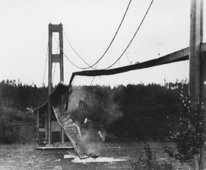
Tacoma Narrows Bridge collapse, caused by improperly designed structure

Vibration of a mechanical system can be descried as an oscillatory motion about an equilibrium point. Certain vibrations of mechanical systems can be considered desirable, such as in musical instruments like a tuning fork or guitar.

However, often times vibrations of mechanical systems are undesirable, producing wasted energy, unwanted noise and catastrophic failures. Therefore it is critical during the product design phase that engineers are able to accurately characterize the vibration response of the system in order to ensure a safe and reliable product for their customers. We accomplish this through comprehensive vibration testing services.

Continue reading Vibration Response of Products

Share This:

Shock Testing: Long Duration Half Sine Shock

Shock testing with long durations can be a challenging endeavor. DES recently had to perform a 35G peak, half sine shock with a 50 millisecond duration. The video below shows this shock test being performed.

This sounds like an easy shock to carry out because a peak of 35G is low compared to many shocks. However, this is a difficult shock to perform because 50 milliseconds is a long duration. Most typical shock durations are less than 20 milliseconds.

A half sine shock impulse has the shape of a half sine wave. More details can be found elsewhere on our blog, in an article titled “Classical Shock Testing“.

Continue reading Shock Testing: Long Duration Half Sine Shock

Share This: