MIL-STD-810 Combined Environments Testing

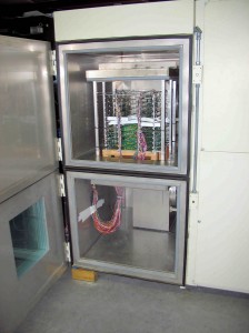
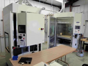
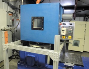
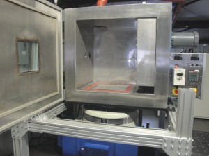
MIL-STD-810, Method 520 Combined Environments Testing is performed to evaluate the synergistic effects of temperature, altitude, humidity, input electrical power, and vibration on airborne electronic and electro-mechanical material. Combined environments testing is critical as it may induce failures that would not be exhibited during individual environment testing.

Additionally, the combined environments can amplify stresses, making this testing more reflective of real-world conditions than testing each environment separately. It’s important to note that MIL-STD-810 Combined Environments Method 520 is not intended as a replacement for methods 500, 501, 502, 507 and/or 514 unless specifically tailored and specified in customer requirements. The latest revision of the Combined Environments Test protocol is Method 520.5 from MIL-STD-810H.

DES is the right choice because we are a MIL-STD-810 accredited lab and will help you navigate through Method 520 Combined Environments testing. 

Some of the Failures caused by Combined Environments are:

  • Shattering of glass vials and optical material.
  • Binding or loosening of moving parts.
  • Separation of constituents.
  • Performance degradation in electronic components due to parameter shifts.
  • Electronic optical (fogging) or mechanical failures due to rapid water or frost formation.
  • Differential contraction or expansion of dissimilar materials.
  • Deformation or fracture of components.
  • Cracking of surface coatings.
  • Leakage of sealed compartments.
  • Failure due to inadequate heat dissipation.
  • If the material is powered, component over-temperature failures.
  • Circuit Card Assembly failures due to short circuiting.
  • Failure of Electromagnetic Interference (EMI) filters.
  • Errors due to input electrical power frequency variances.

Method 520 Combined Environments has three Procedures

Note: It is recommended that single environment tests be performed prior to these procedures to verify system performance under discrete environmental parameters.

  1. Procedure I – Engineering Development.  Procedure I is used to find design defects in new or modified equipment while it is still in the development stage.  After anomalies are found, a root cause analysis is performed to determine the corrective action.  Subsequent testing may be performed to aid in the root cause analysis.  The subsequent tests may use higher stress levels than the product is likely to encounter on a regular basis in the field.  Test durations are based on the time required to induce expected failure modes.  This procedure is not a substitute for Environmental Stress Screening (ESS) or Highly Accelerated Life Testing (HALT).
  2. Procedure II – Flight or Mission Support.  This procedure is performed in preparation for a specific mission scenario.  It can also be used to troubleshoot field returned materiel exhibiting specific mission problems.  The damage accumulation in Procedure II should be no faster than in normal operational or flight testing.  Test durations should be the same as the design mission or, if troubleshooting, sufficient to identify materiel anomalies.  This procedure is not intended to be used in lieu of Procedure III. 
  3. Procedure III – Platform Envelope.    The Platform Envelope test is intended to verify compliance with specific platform/equipment specifications.  This testing utilizes the most significant combination of environmental stress conditions.  A minimum test duration of 10 cycles is required. 

Why Choose DES for MIL-STD-810 Combined Environments Testing

When it comes to MIL-STD-810 Combined Environments Testing, DES is uniquely qualified:

  • DES has the experience to run MIL-STD-810 Method 520 Combined Environments tests .
  • Our lab is A2LA accredited to MIL-STD-810.
  • DES has state-of-the-art equipment to perform MIL-STD-810 comprehensive combined temperature, altitude, humidity testing and other combined environment tests. 
  • With extensive experience in Method 520 testing, DES ensures thorough evaluation and precise identification of potential failure modes.

Contact us today to discuss your MIL-STD-810 testing with one of our engineers. 

Share This:

MIL-STD-810 High Temperature Testing

MIL-STD 810, Method 501 High Temperature Testing is used to evaluate the effects of high temperature conditions on performance, materials, and integrity.  Method 501 is applicable for temperature testing products that are deployed in areas where temperatures (ambient or induced) are higher than standard ambient.  Note, the latest revision of this method is 501.7 from MIL-STD-810H.

Method 501 is limited to evaluating the effects of relatively short-term (months, as opposed to years), even distributions of heat throughout the test item. This method is not typically practical for evaluating materials where solar radiation produces thermal gradients or photochemical effects.  Method 505 is used to test the effects of solar radiation.  It is also not practical to evaluate degradation that occurs from continuous long-term exposure to high temperatures where synergetic effects may be involved.

The following are typical failures that could occur from products used in high temperature environments.

  • Parts bind from the differential expansion of dissimilar materials.
  • Lubricants become less viscous; joints lose lubrication by the outward flow of lubricants.
  • Materials change in dimension.
  • Packing, gaskets, seals, bearings, and shafts become distorted, bind, and fail causing mechanical failures.
  • Gaskets display permanent sets.
  • Closure and sealing strips deteriorate.
  • Fixed-resistance resistors change in values.
  • Electronic circuit stability varies with differences in temperature gradients and differential expansion of dissimilar materials.
  • Transformers and electromechanical components overheat.
  • Operating/release margins of relays and magnetic or thermally activated devices alter.
  • Shortened operating lifetimes.
  • High pressures are created within sealed cases (batteries, etc.).
  • Discoloration, cracking, or crazing of organic materials.
  • Out-gassing of composite materials or coatings.
  • Failure of adhesives.

MIL-STD-810 Method 501 Tests: High Temperature Procedures

  1. Procedure I – Storage.  Procedure I is for testing products that are stored at high temperatures.  After the high temperature storage test is completed, an operational test at ambient conditions is performed.  Procedure I can be either a cyclic temperature test or a constant temperature test. 
  2. Procedure II – Operation.  Procedure II is used to investigate how high temperatures could affect the performance of items while they are operating.  Temperature Procedure II can be performed as either a cyclic temperature test or a constant temperature test. 
  3. Procedure III – Tactical-Standby to Operational.  This temperature procedure evaluates the material’s performance at normal operating temperatures after being presoaked at high non-operational temperatures.  An example of Procedure III is a product that is stored in an enclosed environment that develops high internal temperatures before being removed and then operated in a relatively short period of time.

What is the procedure for MIL-STD-810 High Temperature Testing? 

First, identify the high temperature levels, test conditions, and applicable procedures. DES can help determine the appropriate temperature ramp rates and durations of the tests based on the equipment’s intended use and the operating environmental conditions.  Consider the following climatic temperatures from Table 501.7-I. (MIL-STD-810H):

Design TypeLocationAmbient Air oC (oF)Induced2 oC (oF)
Basic Hot (A2)Many parts of the world, extending outward from the hot dry category of southwestern United States, northwestern Mexico, central and western Australia, Saharan Africa, South America, Southern Spain, and southwest and south central Asia.30 – 43

(86 – 11)
30 – 63

(86 – 145)
Hot Dry (A1)Southwest and south central Asia, southwestern United States, Saharan Africa, central and western Australia, and northwestern Mexico.32 – 49

(90 – 120)
33 – 71

(91 – 160)
Table 501.7-I from MIL-STD-810H

Next, determine whether a constant temperature test or a cyclic temperature test is appropriate.  Constant temperature testing is used only for items situated near heat-producing equipment or when it is necessary to verify the operation of an item at a specified constant temperature.  The duration for constant temperature test temperature is at least two hours following test specimen stabilization.

For cyclic exposure, there are two 24-hour cyclic profiles contained in Tables 501.7-II and 501.7-III.  The number of cycles for the Procedure I storage test is a minimum of seven to coincide with the one percent frequency of occurrence of the hours of extreme temperatures during the most severe month in an average year at the most severe location.   The minimum number of cycles for the Procedure II operational testing is three. This number is normally sufficient for the test item to reach its maximum response temperature.

You can trust the DES MIL-STD-810 High Temperature Testing lab

Advantages with DES : 

  • DES is A2LA accredited to MIL-STD-810, Method 501 High Temperature Testing
  • DES has extensive experience running MIL-STD-810 Method 501.7 high temperature Tests
  • DES has multiple temperature chambers capable of performing MIL-STD-810 high temperature compliance testing

Contact us today to to discuss testing your product in our MIL-STD-810 accredited Test Laboratory. 
Share This:

Thermal Shock Testing – Temperature Cycling

ThermoShockThermal shock testing also called temperature shock testing or temperature cycling exposes products to alternating low and high air temperatures to accelerate failures caused by repeated temperature variations during normal use conditions. The transition between temperature extremes occurs very rapidly during thermal shock testing, greater than 15 °C per minute. Alternatively, temperature cycle testing uses slower rates of change between high and low temperatures. The failure acceleration rate for thermal shock testing is determined by the Coffin-Manson equation as previously discussed in DES’s blog article Temperature Cycling Testing: Coffin-Manson Equation.

Equipment with single or multiple chambers may be used to perform thermal shock testing. When using single chamber thermal shock equipment, the products or samples remain in one chamber and the chamber air temperature is rapidly cooled and heated. This usually results in a slower rate of change in the product response temperature as the entire chamber must be cooled down and heated up. However larger products can be tested in single compartment chambers. Some equipment uses separate hot and cold chambers with an elevator mechanism that transports the products between two or more chambers. This results in a more rapid rate of change in the air temperature. However, there is a limit to the size and weight than can be put in a chamber with an elevator mechanism.  DES has both types of chambers for thermal shock testing.

Continue reading Thermal Shock Testing – Temperature Cycling

Share This:

What Equipment Is Used For HALT?

HALT Chambers

Figure 1 - DES’s HALT Chambers
Figure 1 – DES’s HALT Chambers

Specialized test chambers are needed to perform a HALT. Typical HALT chambers are shown in Figure 1. The specification for HALT chambers is typically the following:

Liquid nitrogen (LN2) is used to cool the air temperature in HALT chambers. This allows for very rapid temperature changes of 60°C per minute and a cold temperature extreme of -100°C.

HALT chamber heating is provided by high power resistive heating elements that can produce changes of 60°C per minute and a hot temperature limit of +200°C.

Continue reading What Equipment Is Used For HALT?

Share This:

Delserro Engineering Solutions Featured in Desktop Engineering

Delserro Engineering Solutions (DES) was honored to be featured in a recent article discussing the capabilities of engineering testing companies. The article highlighted the benefits, in terms of both design and cost, of adequately testing designs, preferably as early in the process as possible. It also discussed the ins and outs of partnering effectively with a reliability testing facility.

The goal of this article was to teach product developers how to get the most bang for their testing buck; a goal that aligns perfectly with DES’s philosophy. No matter what your testing needs are, be they HALT, HASS, or other environmental or stress tests, DES is able to help you design and implement the most comprehensive and accurate test possible. As always, our client’s success is the source of our satisfaction.

Continue reading Delserro Engineering Solutions Featured in Desktop Engineering

Share This:

DES Increases Combined Temperature & Vibration Testing Capabilities

Vibration Testing - Delserro Engineering SolutionsVibration Testing - Delserro Engineering SolutionsDES added another larger AGREE Chamber to perform Combined Temperature and Vibration Testing. This gives DES additional capability to perform combined environmental testing on larger products. DES has performed Combined Temperature and Vibration Testing on car engine sensors, helicopter sensors and outdoor heavy industrial products. Some of the test specifications include MIL-STD-810 and General Motors GMW 3172.

The Equipment Capabilities Are:

  • Combined shock or sinusoidal, random, mixed mode vibration and temperature
  • Temperature range from -80°C to +180°C (-112°F to +356°F)
  • Temperature rate of change up to 20°C/minute
  • 9 cubic feet interior work space, cvo

To learn more about our combined temperature and vibration testing services, visit our website, and be sure to contact us if you would like to find out how our services can work for your products.

Share This:

Recent Testing Projects

We had many interesting test projects at Delserro Engineering Solutions this past month:

  • We completed a Pyroshock test on our Mechanical Impact Pyroshock Simulator (MIPS) on equipment that will fly into outer space.
  • On the other end of the altitude spectrum, we completed environmental testing of components that will be used in submarines to MIL-E-917.  MIL-E-917 is a military specification for Naval shipboard electric power equipment.
  • In the middle of the altitude range, we performed combined temperature and vibration testing on sensors that will be used in automobile engines to specification GMW 3172.  GMW 3172 is a General Motors Specification for electronic component durability.

The following is a sample of some additional testing projects we have completed recently:

Share This:

Lead Free Solder Reliability Issues and Test Methods

This article discusses the reliability challenges of switching over to lead-free solder and the test methods used to demonstrate reliability, written by Gary Delserro and published in Evaluation Engineering Magazine.  Click on the link to download the article in PDF, Lead Free Solder Reliability Issues & Test Methods.

Environmentally friendly is a term rapidly invading the electronics industry.

The electronic industry will be facing great challenges over the next few years as the solder used in electronic products is migrating toward lead-free.  This is being driven by mandates in Europe such as Waste Electrical and Electronic Equipment (WEEE) and Restrictions of Hazardous Substances (RoHS) and similar ones in Japan.  There also is a great deal of pressure in the US to do the same.

Continue reading Lead Free Solder Reliability Issues and Test Methods

Share This: