Mass Air Flow Sensors (MAFS) are used to measure the mass flowrate of air entering engines in newer model cars. The mass air flow information is transmitted to the engine control unit (ECU) to balance and deliver the correct amount of fuel mass to the engine. These sensors operate in a very harsh environment, a car engine compartment! Testing their reliability and proving their durability is a very difficult task.
- Mass Air Flow Sensors (MAFS) Combined Temperature Vibration Testing
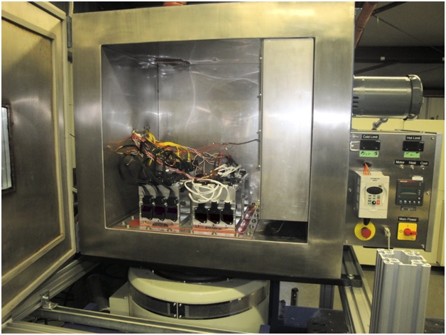
DES was awarded multiple contracts to perform combined temperature and vibration reliability testing of Mass Air Flow Sensors from various automotive part manufacturers and from a major auto parts supplier.
The applicable test specification was GMW 3172, a General Motors Specification for electronic component durability. The test requirements in GMW 3172 were 13 Grms random vibration from 10 to 2000 Hz. Simultaneously with the vibration testing, DES’s AGREE Chamber subjected the MAFS’s to temperature cycles between -40 °C and +125 °C. In addition to the harsh temperature and vibration environment, the sensors were electrically powered and monitored for operation or failure during the test. These harsh conditions had to be run for at least 44 continuous hours per axis along three different axes. Sometimes they were run for longer durations. Many sensors were tested simultaneously which added to the challenge. Finally, a bench air flow tester was used to perform calibrated air flow measurements after each axis to verify the electrical output of each sensor.
This case study shows the advanced capabilities of DES to complete the most difficult temperature and vibration test projects.