Classical shock testing consists of the following shock impulses: half sine, haversine, sawtooth, and trapezoid. Pyroshock and ballistic shock tests are specialized and are not considered classical shocks. Classical shocks can be performed on Electro Dynamic (ED) Shakers, Free Fall Drop Tower or Pneumatic Shock Machines. The parameters required to define a shock test are peak acceleration expressed in G’s or m/sec^2, shape of the impulse, and duration in milliseconds. A classical shock impulse is created when the shock table changes direction abruptly. This abrupt change in direction causes a rapid velocity change which creates the shock or acceleration impulse.

Classical shocks are applied along one direction and one axis at a time. Most specifications require the product to be shocked in both the positive and negative directions along each axis. If shock tests are performed on an ED shaker, the shaker can reverse polarity and perform the shock along both directions of each axis without rotating the fixture and specimen. When performing shock testing on a shock machine, the machine can only apply shock in one axis and one direction. The fixture and specimen must be rotated to apply shocks along different directions and axes.
A typical shock test setup using a pneumatic shock machine is shown in Figure 1. DES can also perform shock testing using an ED shaker and drop tower.
Performing shock tests on a shock machine is much different than using an ED shaker. To create an impulse on a shock machine, the shock table is raised upward to a predetermined height. The table is released then falls or accelerates downward impacting a shock programmer. The table bounces off the shock programmer changing its direction and velocity very rapidly. Finally, the table is stopped before a second impact occurs. The shock programmer is typically rubber or felt material, lead pellets or specialized gas cylinders. The magnitude and duration (period) of the velocity change is what determines the peak G level and duration of the shock impulse. The type of shock impulse is a result of the type of shock programmer that is used.The drop height and programmer thickness can be initially estimated with calculations, however the final test setup is done by experimenting with the machine.
When performing shocks on an ED shaker, the controller software determines how to move the shaker table and create the impulse. The user only has to enter parameters in the software such as the shock type, G Level and duration. No shock programmers are used. The table is abruptly moved by the ED shaker and controller.
Below are some descriptions and samples of shocks performed by DES. DES can perform classical shocks to thousands of G’s with durations from 0.2 to 70 milliseconds. An important note in shock testing is that a greater velocity change (or harder impact) is required as the duration increases for a given G level. Thus, not all G level and duration combinations can be performed.
Half Sine Shock Test
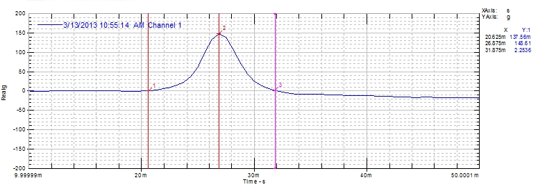
A Half Sine Shock impulse has the shape of a half sine wave. Figure 2 shows a typical half sine shock performed by DES. The shock in Figure 2 is approximately 150 G peak acceleration with a duration of 11 milliseconds. The shock programmers for half sine shocks are usually rubber or felt.
Haversine Shock Test
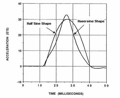
There is not much difference between a half sine shock and a Haversine Shock. A half sine pulse shape is a little more rounded than the haversine pulse shape as seen in Figure 3. The ED shaker controller can differentiate them, however it is hard to differentiate them on a shock machine in DES’s opinion.
Sawtooth Shock Test
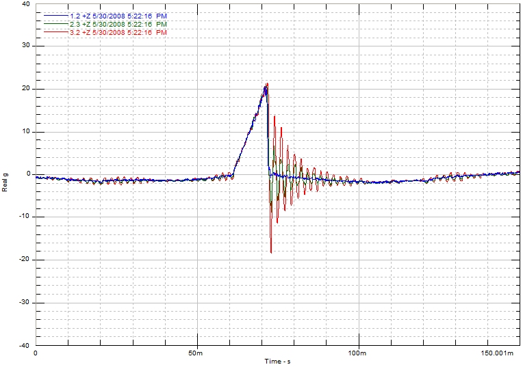
A Sawtooth Shock has the shape of a triangle similar to the tooth of a saw blade. Figure 4 shows a typical sawtooth shock performed by DES. The shock in Figure 4 is approximately 20 G peak acceleration with a duration of 11 milliseconds. The blue trace was on the base of the fixture while the red and green where the response of the product under test. Notice the ringing of the product in the red trace after the shock was applied! Shock programmers for sawtooth shocks are typically deformable lead pellets.
Trapezoid (Rectangular or Square) Shock Test
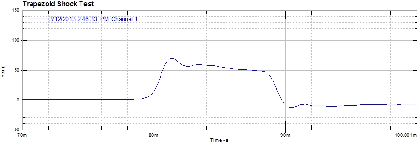
A Trapezoid Shock impulse is also called a Rectangular or Square Shock. A trapezoid shock has the shape of a rectangle or square. A typical trapezoid shock performed by DES is shown in Figure 5. The trapezoid shock in Figure 5 is approximately 50 G peak acceleration with a duration of 10 milliseconds. Note the sides of trapezoid shocks have some rise and fall time so they are not vertical. The shock programmers for trapezoid shocks are usually aluminum honeycomb material or gas cylinders.
I have an optical assembly needing to withstand shock under the following conditions
• Mechanical Shock, 500m/s^2 peak half sine wave, 6ms duration, 10 shocks in each of 6 axes, 60 total shocks
We are trying to run a quick and dirty shock test by mounting a board to some cabinet drawer slides and using some springs to create the load. We pull back on the slide and release. It hits a solid steel block as a stop and decelerates in a few milliseconds. We are calculating approximately 15-25 G of force using an accelerometer mounted to the board. Is this even a close approximation to your half sine test? We know we have to run the full environmental tests to be accurate but we want at least a rough indication of whether our assembly has a chance of withstanding the tests. We have had problems with adhesive failure in either thermal cycling or vibration/shock testing.
I am travelling so please post a reply and email me directly.
Thanks for the assist on this!
Greg
It is probably not similar. There is a frequency component to shocks also. For a half-sine pulse,the relation of the time duration of the pulse to the frequency is 1/2T = f, where
T = time duration, seconds
f = frequency, Hz
OK,
Say I have an accelerometer attached to a drop tower carriage with a DUT.
The accelerometer weighs 10grams, the DUT weighs 1,000grams, and the acceleration read by the accelerometer is 200G.
Why do I keep getting 2G for the DUT acceleration?
Here are the specifics:
Force (F)=ma
Accelerometer mass (m)=10g
Acceleration read by accelerometer (a)=200G
Force acting upon accelerometer (F)= 2000grams/force
Acceleration (a)=F/m
So
DUT mass (m)=1Kg
DUT G Value (2000grams/force)/1Kg=2G?
Am I doing something wrong here?
The acceleration for a drop table is calculated by the change in velocity of the table, a = dv/dt. Accelerometers typically output voltage. Check that you have the correct sensitivity for your accelerometer in millivolt/g.
The simple answer is that if there is no relative motion between the accelerometer and the DUT then they should have the same acceleration (rigid bodies). In the calculation, the force on the accelerometer is used to calculate the acceleration of the DUT which is wrong.
Agreed