This is part two of a series of blog posts concerning the MIL-STD 810 Shock Section, Method 516. This blog was written with reference to MIL-STD-810G w/Change 1 dated 15 April 2014. DES has the experience and expertise to run your MIL-STD-810 test. For more information, please check out our DES shock testing services page and our other MIL-STD-810 shock testing blog articles:
MIL-STD 810, Method 516, Shock Testing Overview
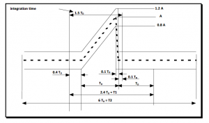
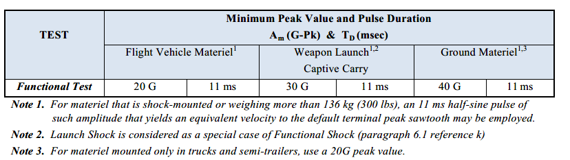
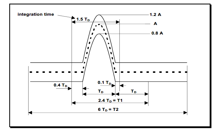
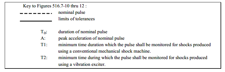
Shock testing according to Procedure I of MIL-STD 810, Method 516 is intended to test products while they are operating to see if any functional problems occur and to determine if they survive without damage. The applied shocks usually represent those that may be encountered during operational service. This article will focus on the shock test condition when measured field data is not available and the testing will use classical shock impulses. The terminal peak sawtooth is the default classical shock pulse to be used for this condition. Figure 516.7-10 from MIL-STD-810 shows its shape and tolerance limits. Table 516.7-IV contains the terminal peak sawtooth default test parameters for Procedure I -Functional Test. In limited cases a half sine shock impulse is specified. Its shape and tolerance limits are shown in Figure 516.7-12.
The product should be mounted to the machine or fixture as it would in normal use. So, if it is bolted using a flange, then it should be attached to a fixture using this flange with the same size and number of bolts.
The typical shock testing procedure is to first perform calibration shocks using a mass similar in size, weight and center of gravity (CG) of the product to be tested. Most commonly a non-working mechanical product is used for this purpose. Once the desired shock requirements are met with the calibration mass, the mass is removed and the product to be tested is installed on the shock test machine or fixture. Since this is a functional shock, the product must be operating and monitored for anomalies. Therefore, before the shock is applied, the product must be energized and the monitoring equipment should be operating. After each shock, operation of the test item is verified and it is inspected for visual damage.
The most common requirement is to perform 3 shocks along both the positive and negative directions along 3 orthogonal axes. This is a total of 6 directions and 18 shocks. When setting up to perform shocks in each direction, calibration shocks with the mass simulant are performed first because the weight, CG and product response could require different settings on the shock machine. The shocks are performed along both the positive and negative directions of each axis because classical shocks are single polarity.
For more information on Shock Testing or other testing services, contact DES or call 610.253.6637.
will two 100g5mS trapezoidal pulses approximate one 100g11mS trapezoidal pulse in energy for test spec compliance?
No, two 5 ms shocks will not approximate one 10 or 11 ms shock.