This is part one of a series of blog posts concerning the MIL-STD 810 Shock Section, Method 516. This blog was written with reference to MIL-STD-810G w/Change 1 dated 15 April 2014. DES has the experience and expertise to run your MIL-STD-810 test. For more information, please check out our DES shock testing services page.
MIL-STD-810 is a public military test standard that is designed to assist in the environmental engineering considerations for product design and testing. For the purposes of this blog series we will focus on Method 516.7, Shock Testing.
The purpose of shock testing is to:
- Evaluate if a product can withstand shocks encountered in handling, transportation, and service environments
- Determine the product’s fragility level
- Test the strength of devices during a crash situation to verify that parts do not break apart, eject and become a safety hazard
Shock testing failures are a function of the amplitude, velocity, and the duration of the impulse. If a product has a resonance frequency that corresponds with the frequency of the shock, the effects of the shock will be magnified.
Typically shocks in Method 516.7 are limited to a frequency range not to exceed 10,000 Hz, and a duration of not more than 1.0 second. Method 516.7 contains eight test procedures which are summarized in Table 516.7-I.
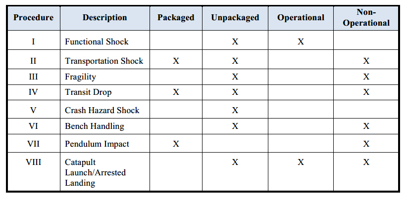
Table 516.7-I from MIL-STD-810G w/Change 1
The differences among procedures is briefly defined below:
- Procedure I – Functional Shock. Procedure I is intended to test products while they are operating to see if any functional problems occur and to determine if they survive without damage. The applied shocks usually represent those that may be encountered during operational service.
- Procedure II – Transportation Shock. Procedure II is used to evaluate products for repetitive shocks from transportation environments. This procedure typically uses a classical terminal peak sawtooth impulse to simulate transportation shocks.
- Procedure III – Fragility. Procedure III is used to determine what shock conditions will cause a product to stop operating, degrade or fail. The shock magnitudes are systematically increased until a problem occurs. This procedure can be also performed at environmental temperature extremes.
- Procedure IV – Transit Drop. This procedure is used to test items that could be accidentally dropped such as when they are removed from a shelve or dropped when handling. The test item is physically dropped onto a hard surface during Procedure IV. The items can be tested inside their transit case or unpackaged.
- Procedure V – Crash Hazard Shock Test. Procedure V is used to test materiel mounted in air or ground vehicles. This procedure is intended to verify that parts do not beak loose which would cause a hazard to occupants or create significant damage to the vehicle.
- Procedure VI – Bench Handling. This procedure is used to test products that may experience shocks on a work bench. Bench handling shocks could occur when items are being repaired or when they are in the process of being packaged. The products are tested in an unpackaged configuration. The drop heights are less than Procedure IV.
Procedures VII and VII are very specialized shock tests. They are briefly mentioned because they are part of Method 516.7, Shock Testing.
- Procedure VII – Pendulum Impact. Procedure VII is intended to test the ability of large shipping containers and their internal contents to resist horizontal impacts from accidental handling.
- Procedure VIII – Catapult Launch/Arrested Landing. Procedure VIII is intended for materiel mounted in or on fixed-wing aircraft that is subject to catapult launches and arrested landings.
The laboratory shock test options are summarized below in Table 516.7-II. The shock test options are divided according to the use of Time Waveform Replication (TWR), drop tests, classical shock pulses, or SRS shocks. TWR is considered to be superior and the most realistic as it is based upon direct replication of field measured data, however it is not usually available. Classical shock pulses are used when TWR data is unavailable. Shock Response Spectra (SRS) refers to cases in which an SRS curve is used for the test specification.
Table 516.7-II – Laboratory Shock Test Options from MIL-STD-810G w/Change 1
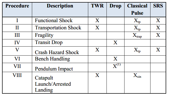
TWR – Time Waveform Replication
Drop = free fall drop event
SRS = Shock Response Spectra
Xtp – terminal peak sawtooth classical shock
Xtrap – symmetric trapezoidal classical shock
Xsin – two-second damped (Q=20) sine burst
Note (1)- Horizontal Impact
It is important that the shock data acquisition instrumentation is adequate to capture the shock impulse. Method 516.7 provides guidelines for the shock test data acquisition system.
To learn more about our shock testing services, please feel free to contact us with your inquiry. Feel free to explore our site to learn about our full line of product testing services, and the test standards that we can help our clients with.