This is another part of a series of blog posts concerning the MIL-STD 810 Shock Section, Method 516. This blog was written with reference to MIL-STD-810G w/Change 1 dated 15 April 2014. DES has the experience and expertise to run your MIL-STD-810 test. For more information, please check out our DES shock testing services page and our other MIL-STD-810 shock testing blog articles:
MIL-STD 810, Method 516, Shock Testing Overview
MIL-STD 810, Method 516, Shock Testing Procedure I – Functional Shock
MIL-STD 810, Method 516, Shock Testing Procedure II – Transportation Shock
MIL-STD 810, Method 516, Shock Testing Procedure III – Fragility
MIL-STD 810, Method 516, Shock Testing Procedure IV – Transit Drop
Crash hazard shocks apply to materiel mounted in air or ground vehicles. Shock testing according to Procedure V of MIL-STD 810, Method 516 is intended to test the strength of products during a crash situation to verify that parts do not break apart, eject and become a safety hazard. Failures of this nature could cause dangerous projectiles that could impact occupants or create significant damage to the vehicle.
This article will focus on the shock test condition when measured field data is not available and the testing will use classical shock impulses. The terminal peak sawtooth is the default classical shock pulse to be used for this condition. Figure 516.7-10 from MIL-STD-810 shows its shape and tolerance limits. Table 516.7-IV contains the terminal peak sawtooth default test parameters for Procedure V – Crash Hazard Shock. In limited cases a half sine shock impulse is specified. Its shape and tolerance limits are shown in Figure 516.7-12.
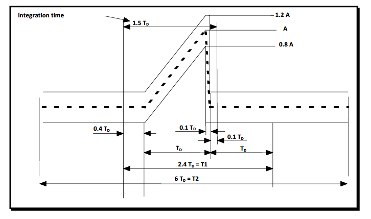
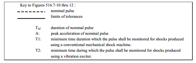
Figure 516.7-10. Terminal peak sawtooth shock pulse configuration and its tolerance limits
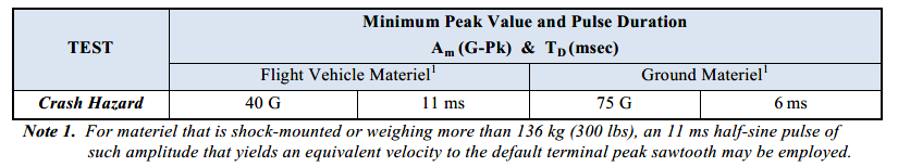
Table 516.7-IV. Terminal peak sawtooth default test parameters for Procedure V – Crash Hazard Shock
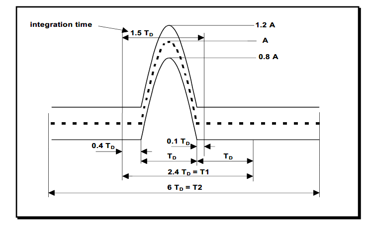
Figure 516.7-12. Half-Sine shock pulse configuration and tolerance limits
The product should be mounted to the machine or fixture as it would in normal use. So if it is bolted using a flange, then it should be attached to a fixture using this flange with the same size and number of bolts.
Typically, calibration shocks are performed first using a mass similar in size, weight and center of gravity (CG) of the product to be tested. Once the desired shock requirements are met with the calibration mass, the mass is removed and the product to be tested is installed on the shock test machine or fixture. The units under test do not have to be operating during crash hazard shocks. After each shock, the test sample is inspected for visual damage. Minor permanent deformations are usually acceptable as long as the product stays intact. Significant damage such as large cracks may be cause for failure if they pose a risk of structural failure.
The most common requirement is to perform 2 shocks along both the positive and negative directions along 3 orthogonal axes. This is a total of 6 directions and 12 total shocks. When setting up to perform shocks in each direction, calibration shocks with the mass simulant are performed first because the weight, CG and product response could require different settings on the shock machine. The shocks are performed along both the positive and negative directions of each axis because classical shocks are single polarity.
For more information on Shock Testing or other testing services, contact DES or call 610.253.6637.